In the preceding section of this series, we discussed the following topics:
Routinely for engineering calculations, it’s common to have a few foundational pieces necessary to begin an analysis process. You don’t need to know an allowable design or material classification to solve an analytical solution and get results. Without stress and strain curve information, you don’t know if those results are accurate.
Up next in this series is:
- Theory Of Failure For Ductile Material analysis
- Maximum Shear Stress Theory (MMS)
- Distortion Energy Theory Of Failure
- Theory Of Failure For Brittle Materials
- Coulomb–Mohr and Modified Mohr Theory:
- The Maximum Normal Stress Theory
- Stress Failure Theories – How to Select the Right One
Mechanical Stress Terminology
When it comes to stress analysis and FEA Simulation, we tend to think of a physical force acting on a cross-sectional area of an object. But, like most things in life, stress is more complicated. There are many different types of stress: normal stress, principal stress, thermal stress, and shear stress are just three examples.
Combining them gives a true measure of the object’s overall stress capacity to determine if overall stress has exceeded the yield strength of the material. That is where an FEA model is very helpful.
To take proper action to change the design or if no action is required, we need to understand what each type of stress tells us. To understand stress terminology, we need to know what it means.
Let’s look into stress terminology in more detail.

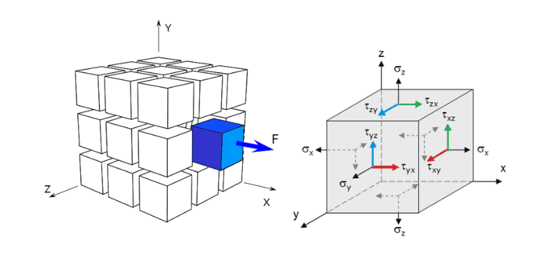
Normal Stresses: As shown in the figure above, stress acts on the face with a subscript. Stress is positive, and compression is negative.
\sigma= \sigma_x,\sigma_y,\sigma_z
When a structure is loaded with a force, it experiences normal stresses. These stresses can result in a design failure or cause added maintenance. Failure occurs when the stress exceeds the strength of the material. Stress is calculated by:
\sigma = \frac{F}{A} = \frac{M*c}{I}Stress can also be measured by strain, calculated by multiplying strain and the modulus of elasticity.
E = \frac{Stress} {Strain}The modulus of elasticity is a number that is defined by the ratio of applied stress to corresponding strain within the elastic limit. Physically it indicates a material’s resistance to being deformed when stress is applied to it. The value of elastic modulus is higher for stiffer materials.
- Bending stress occurs when an object is forced to follow an arc, such as bending a spoon with your hands.
- Torsion Stress describes a twisting motion that causes stress on an object, like turning a doorknob.
- Compression stress describes pressure applied to an object in any direction, such as squeezing a sponge.
- Shearing Stress describes a horizontal force that acts upon an object parallel to its face, such as the lateral movement of a car driving down a road or slipping off a chair and onto the floor.
- Tension Stress describes a pulling force applied to an object at right angles to its face, such as the weight of a roller coaster car pulling on its track.
- Shear Stresses: Shear stresses are defined as forces (shearing force) perpendicular to the axis of a material. This force can be due to internal or external sources. A material will experience shear stress if deformed by tension, compression, or both. It can also happen if tension and shearing are deforming the material.
While shearing may occur in any direction, it usually occurs parallel to the deformation plane. The shearing stress will only act on the top layer of material and may cause failure at that point.
Shear stress has two subscripts:
\tau_{xy}, \tau_{yz}, \tau_{xz}- The first subscript denotes the face on which the stress acts.
- The second subscript denotes the direction on that face.
Static Equilibrium: For an object under static equilibrium where,
\tau_{xy} = \tau_{yx}, \tau_{xz} = \tau_{zx}, \tau_{zy} = \tau_{yz}Resulting in six independent scalar quantities. These six scalars can be arranged in a 3 X 3 matrix, giving us a stress tensor below:
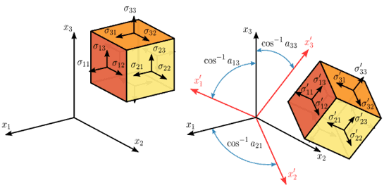
\sigma = \sigma_{ij}=\begin{Bmatrix} \sigma_x & \tau_{yx} & \tau \\ \tau_{xy} & \sigma_y & \tau_{zy} \\ \tau_{xz} & \tau_{yz} & \sigma_{z} \end{Bmatrix}The stress state above is a second-order tensor since it is associated with two directions.
Who cares? We don’t need some fancy mathematics to solve a simple stress problem.
Unfortunately, I am unaware of too many well-excepted failure theory that uses normal stress. Most failure theories use principle stresses. And you have to convert normal to principal stresses to apply failure theory. There are three planes for every point inside a body under static equilibrium, called the PRINCIPAL PLANES, where the stress vector is normal to the plane, and there is no shear component.
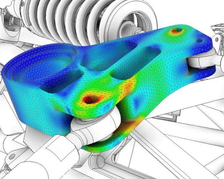
These normal stress vectors are called principal stresses. For FEA structural analysis, this is a very important fact. When performing analysis by hand, it’s realistically impossible to calculate the stress at every point inside a body. However, With FEA, the post-processor finds a solution at every node.
This is done by taking the derivative of the transformation equations for plane stress. This leads to:

Okay, That Is Great. Why Do I Care?
Engineers need to define stress correctly to improve safety margins in the design of structures. The main function of solid mechanics is to satisfy all requirements for design. Using incorrect stress terms can lead to poor quality work and expensive redesigns. The correct stress terminology provides a clear definition for accurate calculations, design changes, and failure analysis.
Stay tuned for Part 4 of this series as we dive into the theory of Failure for Ductile Materials – Maximum Shear Stress Theory (MMS).
I’d love to hear what you think about these different Mechanical Stress Terminologies. Should we consider any different types of stress? Let me know in the comments below.


