We outlined why simulation is no longer a luxury in two previous posts. In Parts 1 & 2, we discussed the need for an efficient design process and how simulation technology leads to an optimized and validated design. But without knowing what the final result (answers) mean, there is no way to perform an FEA structural analysis or stress analysis. Also, for more of a textbook review of engineering fracture mechanics, we recommend reviewing this PDF from Montana State University.
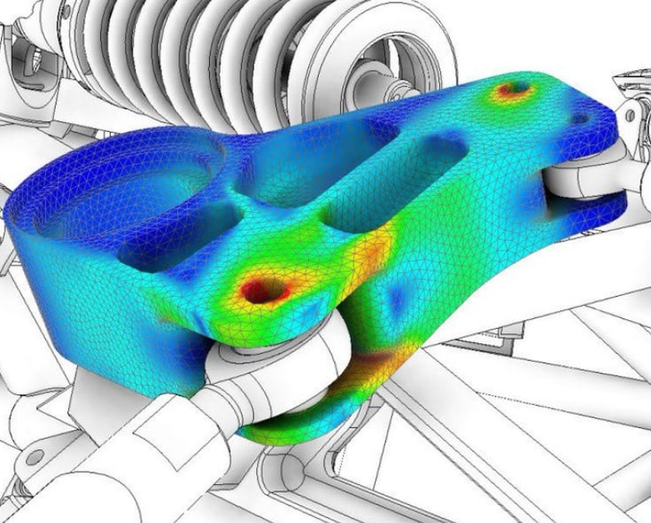
Structural Analysis and Finite Element Analysis (FEA) answers questions about physical behavior. Simply, it is an engineering method that reduces time to market when used during the development process. More importantly, it allows the engineering team to prevent design and reliability issues, resulting in better product design.
Nevertheless, it’s pointless if you don’t know how to interpret the results or apply the wrong Failure Theory to your Structural Analysis or FEA Simulation. Engineers must understand, select, and apply the correct Failure Theory to design any product. This will help us determine the model results from our finite element method (FEM) before taking action.
This series will cover all aspects to know what the answers mean. We will understand allowable stress and determine some best practices to determine design and stress allowables. Then we will move into the following:
- Design Allowable Practices
- Material Classification Practices
- Mechanical Stress Terminology
- Theory of Failure for Ductile Materials:
- Maximum Shear Stress Theory (MMS)
- Distortion Energy Theory of Failure (von mises)
- Theory of Failure for Brittle Materials
- Coulomb Mohr and Modified Mohr Theory
- Maximum Normal Stress Theory
- Static Theories of Failure – How to Select the Right One
Failure Analysis – Design Allowable Practices
To start, we must understand the characteristics of what we are simulating. In many ways, the characteristics of the system and how the parts of that system interact with each other are the most difficult to determine and apply.
Typically, any system characteristics are highly debatable during the conceptual design phase. We can use a handful of tools to figure out these characteristics. Besides other design characteristics, one of the first items that need to be decided and selected is the material properties employed.
What determines a failure when you run a simulation and review the results? Or, to say it another way, what is failure?
Failure of an object is any behavior that renders it unsuitable for its intended use. I cannot count how many times this issue has come to light. The most significant warranty issue I worked on was unforeseen and environmental, leading to millions in yearly warranty repairs.
This definition leads to failure meaning different things to different companies for different products. For example, failure could be functional, meaning the equipment is repairable. However, it could also be a total failure, resulting in an unsafe condition or unable to be repaired.
After setting the relevant factors, we must determine which failure theories are appropriate for the material. Alternatively, it could have some flexibility to be assembled but cannot buckle.
As you can see, it is about balance, and it depends on the reference frame of the engineer and the application. Moreover, in our view, great solutions require great partnerships with all stakeholders.
Before starting any simulation or FEA analysis, there are a few things you should be aware of. The Engineering team must take ownership of any survivorship bias. It seems like it is easy for most of us to do.
We tend to concentrate on the designs that have survived and overlook those that did not. Survivorship bias typically occurs because of a lack of visibility. The Internet of Things and digital transformation will eliminate this lack of visibility as technology advances. However, it is best to look at everything, and below is a quick list:
- Perform a Process and Design Failure Mode and Effects Analysis (FMEA) (Bottom Up)
- Perform a Fault Tree Analysis (Top Down)
- Review the manufacturing methods, processes, and service history
- Comparing failed parts with similar parts that were in operation for their designed service life
- Determine indications of non-specification discontinuities
- Examine associated or mating parts for signs of a future failure
- Identify any abnormal conditions
- Differentiate between isolated and recurring failures
- Did failure occur right away (infant mortality) or after repeated use (fatigue)
- Check assembly details and alignment
- Differentiate between deformed (yielding) and non-deformed (brittle) failures
- Identify possible design flaws or oversites based on the failure mode and usage history
The engineering team must determine the allowable mechanical and thermal stress, displacement (elastic deformation), frequencies, etc. For example, the engineering team might select the allowable stress quantities for the material’s yield or fracture (rupture) points.
How about the stress from the load combination and operational temperature? How will the operational temperature affect the materials employed in the design? There are natural frequencies to avoid in most cases, but can I get away with 29 HZ?
Each allowable must be updated for each design’s intended purpose and the environment they operate in. Each allowable will have appropriate safety factors that address uncertainties in applying boundary conditions and materials, end-use, and manufacturing process effects (Residual Stress).
After setting the appropriate allowable and safety factors, we need to determine which Failure Theories are appropriate for the material in use? We will cover the fundamental Failure Theories in future posts. However, I want to point out that many different failure theories and selecting the correct failure theory depend on the applicable code, material, and application in most cases.
Stay tuned for Part 2 of this series to understand Applied Engineering Failure Analysis Theory and Material Classification Practices.
I’d love to hear what you think about determining stress and design allowable. Let me know in the comments below.