
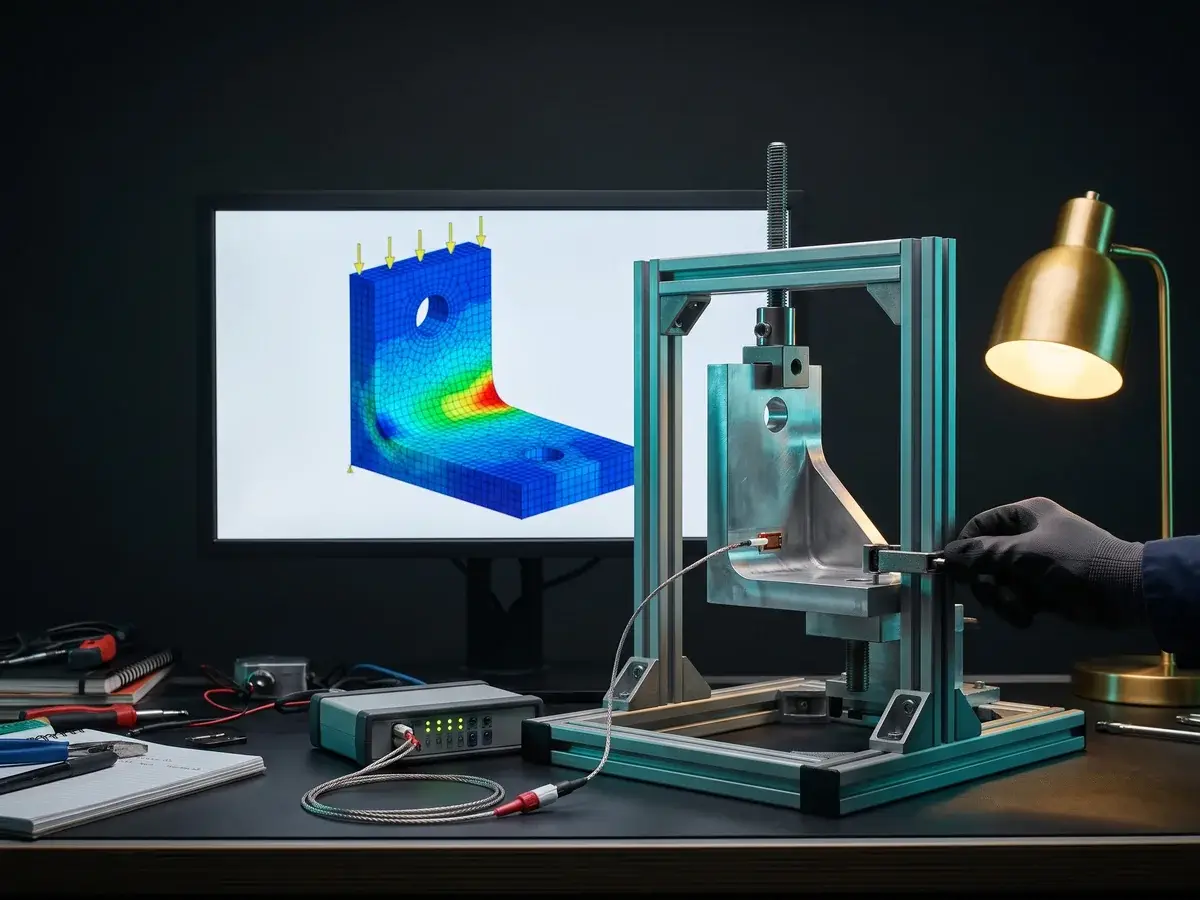
Find stress, fatigue, and buckling risk in the model before tooling, with results you approve at each gate.
Find it before tooling.
Covers
Stress
Fatigue
Buckling
Model flow, pressure drop, and heat transfer to fix the design early, not after the first prototype runs.
Fix flow before build.
Covers
Flow
Pressure
Heat
Couple thermal, structural, and flow loads in one model when a single physics view misses the real failure.
See the coupled risk.
Covers
Thermal
Structural
Flow
Single-point design failures ground fleets and trigger costly program reviews.
Find it before flight.
Applications
Flight FEA
Buckling
CFD
Late validation cycles delay vehicle launches across model-year gates.
Ready for the next gate.
Applications
EV Thermal
Crash
NVH
Promised energy savings disappear when models miss real operating data.
Validate energy savings.
Applications
Turbine CFD
Heat Recovery
Plant FEA
Overcooled data halls inflate PUE and waste energy every hour they run.
Cool only what you need.
Applications
PUE
Cooling CFD
Airflow
Who Writes These Articles, And Where Do The Methods Come From?
Engineers write every finite element analysis article on this page. The people who run PPS projects write about problems they see in real designs. They cover what went wrong, how they checked it, and what they would do next time. The articles teach methods, not sales pitches.
PPS engineers run FEA, CFD, CAD, and DFMA in-house, with testing in-house, at a managed lab, or at your facility. Every design goes through our design QC, and the articles follow the same methods. Each post names its author and shows when it was last updated, so you always know who stands behind each method.
Nick Duff, Co-Founder & Chairman, CEO, is an aerospace stress engineer on flight-critical aerospace and defense programs. Tom Cushing, Co-Founder & CTO, is a licensed Professional Engineer (PE). He leads the tools, methods, and design QC our engineers use from assessment to delivery. You can read their backgrounds on our About page. Spot a mismatch with your project? Tell us, and we will look. We reply within one business day.
Can I Use The Methods In These Articles On My Own Designs?
Yes. Each finite element analysis article explains the method step by step, so you can apply it to your own work today. It covers what to set up, what to check, and what a good result looks like. We write for practicing engineers who know the basics.
There is a limit, though. An article cannot see your loads, materials, schedule or drawings. The same method can mislead you when the inputs are off. That is why ASME V&V 10 sets out how to verify and validate a model. When a design decision, a supplier dispute or a safety margin depends on the answer, get a second look.
Use the articles to plan your next project, to review a report from a supplier, or to train a new engineer. Then have the work checked by an engineer who can see the whole problem. Our free assessment is the first step. You send the data and we review your project scope. You get a roadmap that shows what we would check, change or test next, and why.
What Should I Do If My FEA Looks Wrong?
If a finite element analysis result looks wrong, stop before you act on it. Most bad results start in a few places. The supports may not match how the part is held, or loads sit in the wrong place. The mesh may be too coarse at the hot spot.
Or the material model may ignore yield. Act on a bad result and you can approve a weak part or reject a good one. Either mistake costs money once tooling is cut. So check the model first, as ASME V&V 10 describes. Compare reaction forces with a hand calculation, refine the mesh where stress peaks, and confirm the units.
If the model disagrees with test data or common sense, the model is the problem, not the part. If the decision is close or costly, send us the model, the drawings and what you expected. We sign your NDA or send ours before you share any data. We reply within one business day, and the first step is a free scope assessment that ends with a roadmap.
How Do I Know When To Use FEA Instead Of Physical Testing?
Use finite element analysis when you need to compare many design options fast. It also fits when a test part would be costly, slow or unsafe to build. A model can try loads, materials and shapes that a test rig cannot, and it shows where stress peaks inside the part.
But a model only knows what you tell it. Skip testing on a part where loads, materials or joints are uncertain, and a model error can reach production unseen. Test too early instead, and you pay for prototypes that a model could have ruled out. Either way, your schedule and your budget suffer.
Most designs need both methods. Use the model to narrow the options and find the weak spots. Then test the design that matters to confirm it, as ASME V&V 10 describes. Test data then sharpens the model for the next change. If you are unsure which mix fits your part, send us the drawings, loads and goals. The first step is a free scope assessment that ends with a roadmap.